Main Content
Home
HP Products


HP About
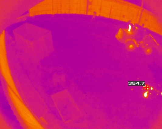
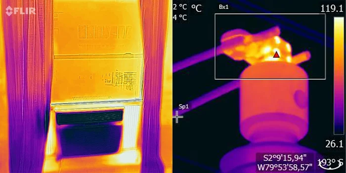
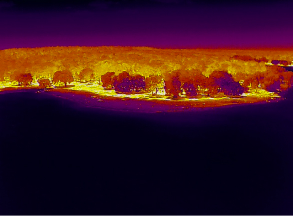
Insights Beyond Human Perception
IMC’s mission is to create category-defining products, which uncover what otherwise cannot be seen, to solve industrial-scale problems that improve our world. Humans only sense a tiny fraction of the information available in the world around them. Modern sensing technology makes much of this hidden world detectable.
HP Outcomes
Outcomes
HP Featured Product
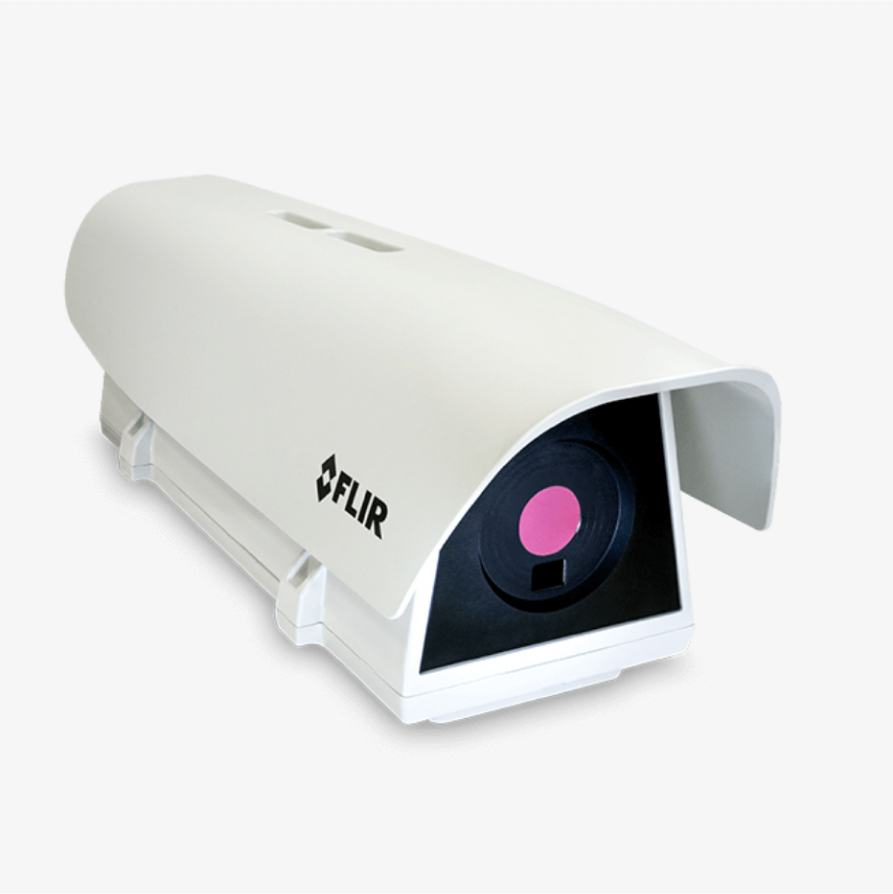
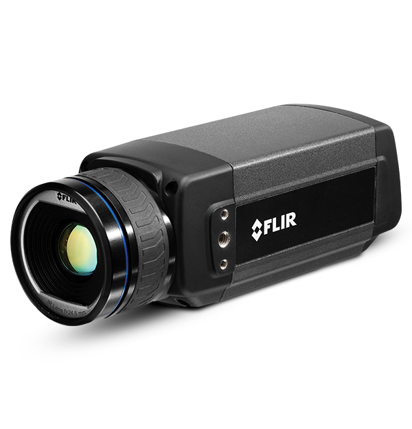
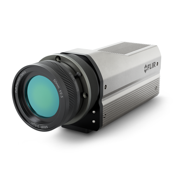
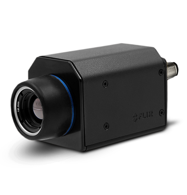
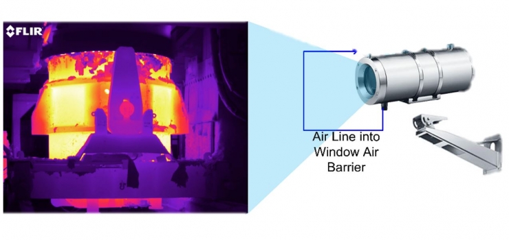
Fixed Thermal Cameras
HP About Us - Slider


HP Business Partner
Business Partners
HP Solutions
Solutions
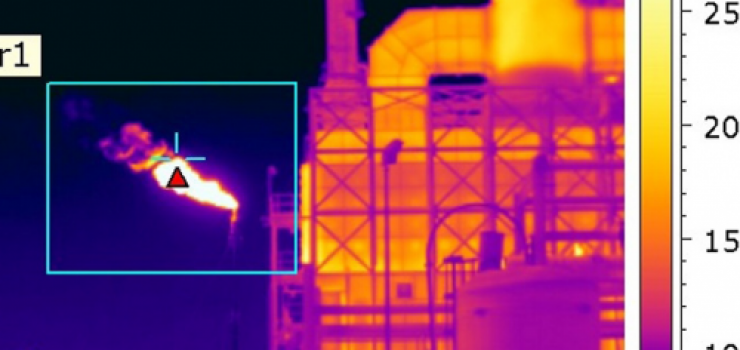
01Thermal Imaging
We collaborate transparently to create unique solutions, maximizing your ROI. With expert support available 24/7.
02Vision Systems
We collaborate transparently to create unique solutions, maximizing your ROI. With expert support available 24/7.

03Automation
We collaborate transparently to create unique solutions, maximizing your ROI. With expert support available 24/7.